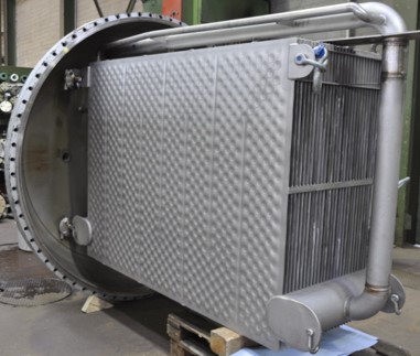
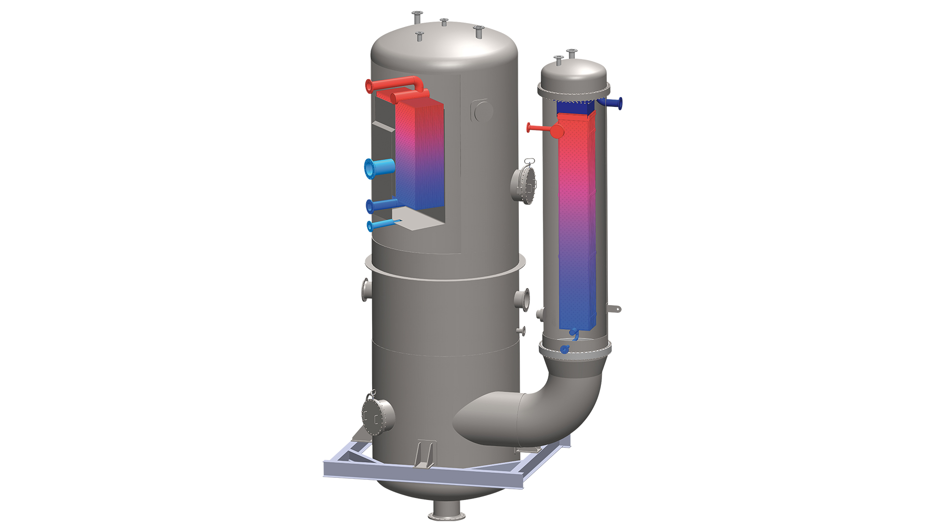
WTP-Head Condenser
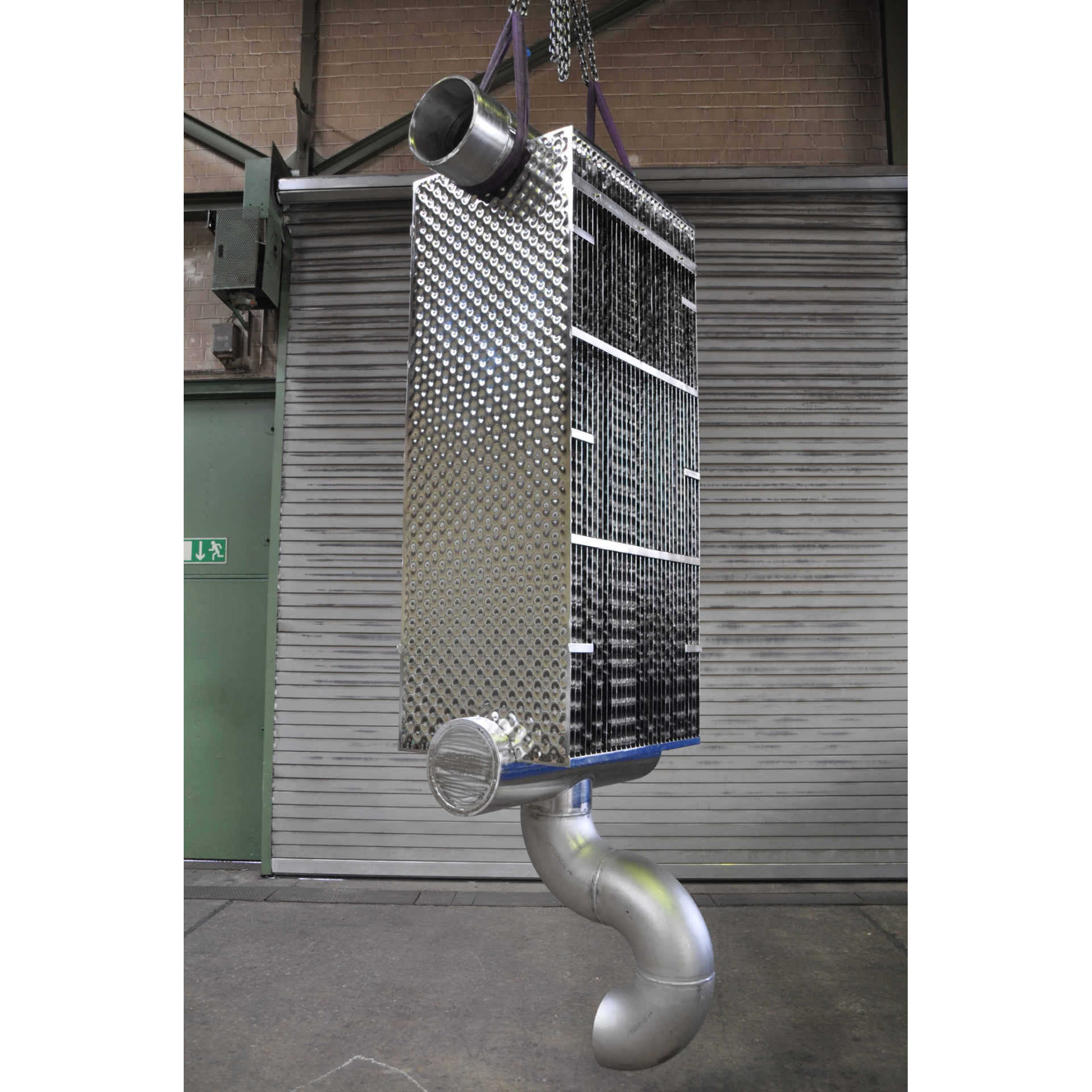
During the condensation of fluids, a vapor mixture initially forms at the lower end of a several meters high column. The vapor mixture streams upwards against the fluid and becomes enriched. In a condenser, the vapor mixture then returns to the liquid state. The condenser is located at the top end of the column, hence the name ‘Head Condenser’. Usually, the condensation takes place at low pressure while the cooling water is highly pressurized. Thick, heavy and costly tubesheets are necessary to withstand the pressure difference in tube bundle condensers. By comparison with tube bundle head condensers, WTP-Head condensers need a smaller installed area of only 25 to 35 % and have a lower weight by up to 50 %. Since the weight puts a strain on the column structure, high-capacity WTP-Head condensers increasingly prevail as head condensers.
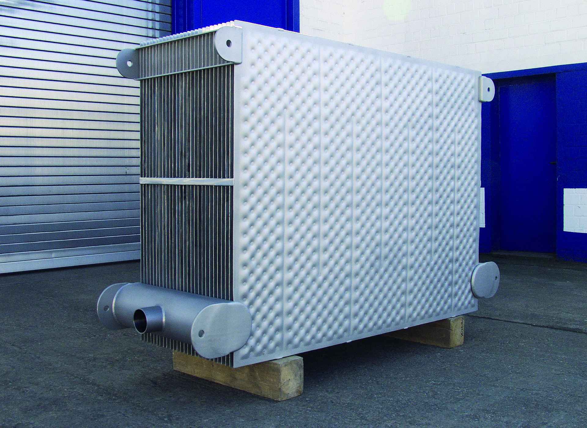
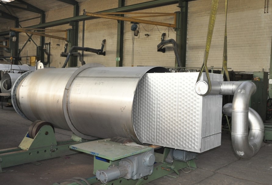
In plate-type condensers, the product usually moves between the plates and the cooling medium moves inside the plates. The lower pressure on the product side determines the wall thickness dimensions of the vessel. WTP-Plates consist of 1,5 to 2,0 mm thick plates, which are connected with circular welding patterns. After expanding the sheets using pressure far above the operating pressure, the cooling water can be safely flow through the evenly spaced pillows. The operating pressure varies between 5 bar and 5 mbar at a temperature from +300 to -25 degrees Celsius. At low operating pressure, the acceptable pressure loss is less than 1 mbar. At such low pressure only a plate condenser can be used. This is achieved by adjusting the distance between the WTP-Plates. However, a high plate distances will be at the expense of condensation. In such cases, a larger exchanger surface needs to be provided. The heat transfer coefficient (α-value) on the secondary side is adjustable by changing the extent of bulging of the inner plate by adjusting the expanding pressures, and the choice of the circular welding pattern. On the cooling water side, there also is a trade-off between high α-values and high pressure losses. On the cooling water side, heat transfer coefficients (α-values) of 500 to 8,000 W/(m²K) and higher are easily achieved. If the α-values on the product side are considerably lower, higher α-values on the coolant side will have no significant effect on the thermal transmittance coefficient k and will consequently not affect the heat exchange.
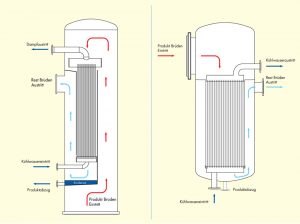
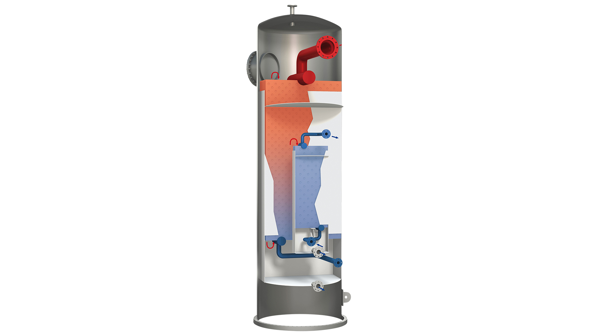
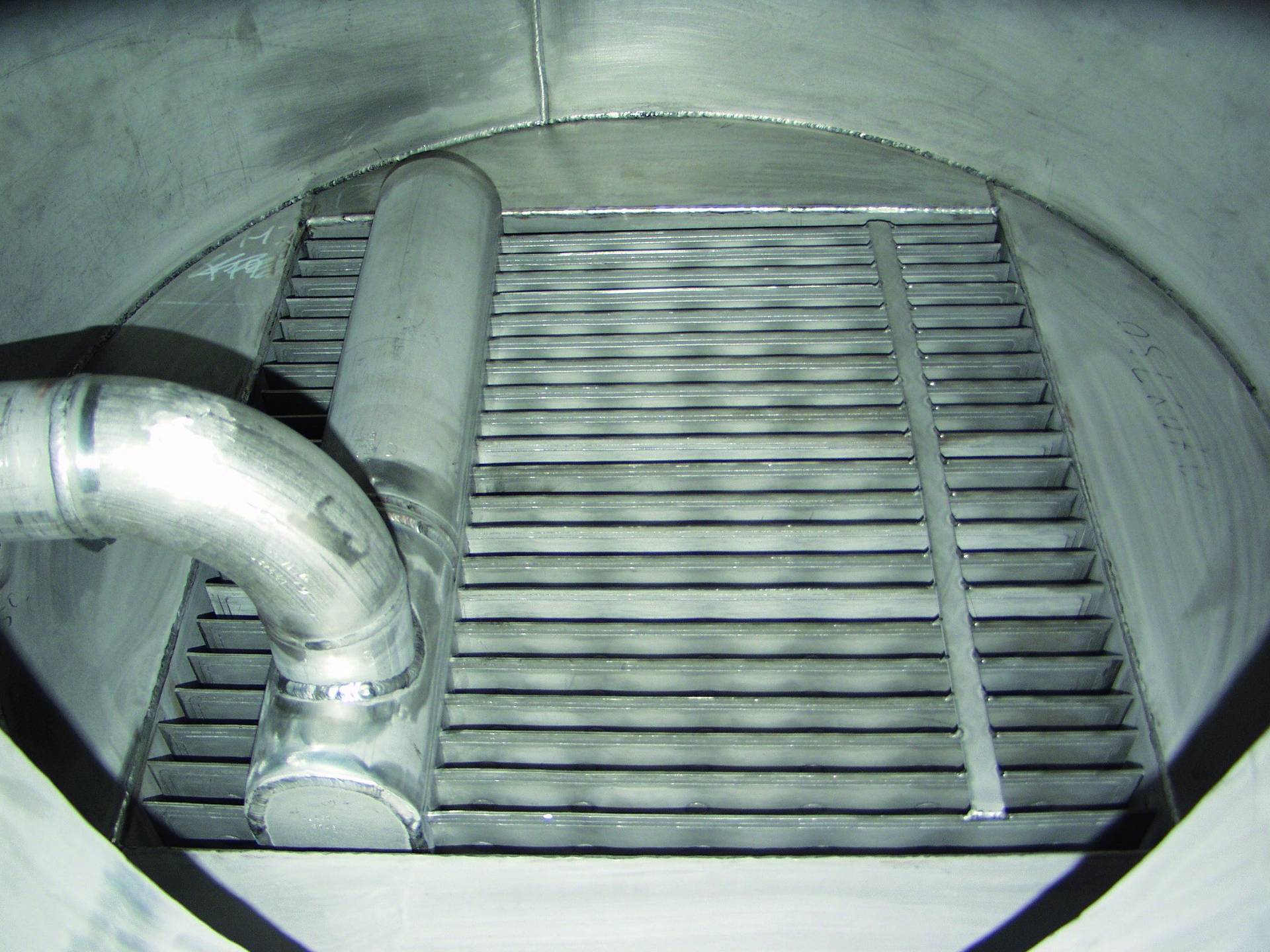
WTP-Head Condenser design drawing / Fin Condenser design drawing
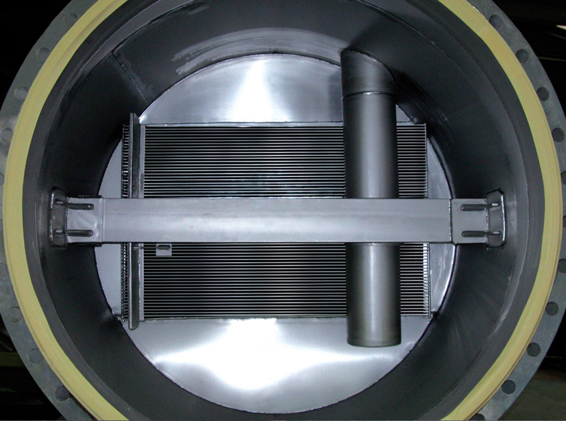
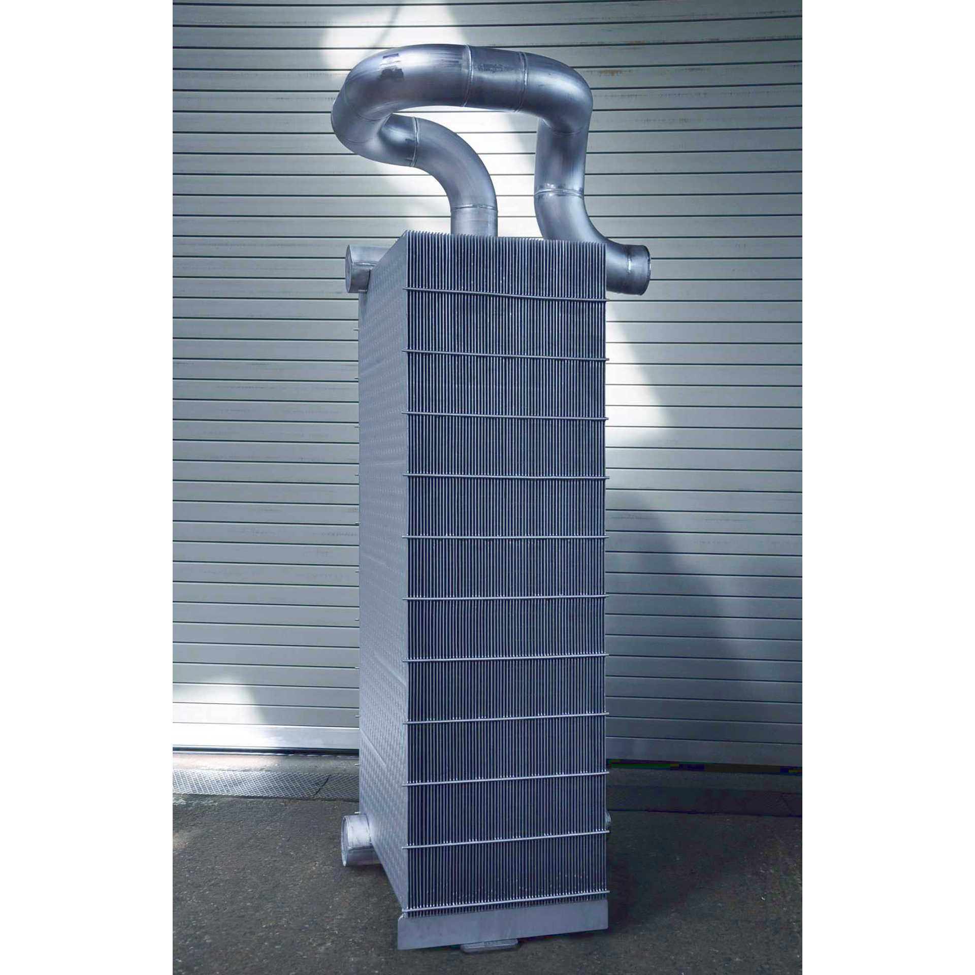
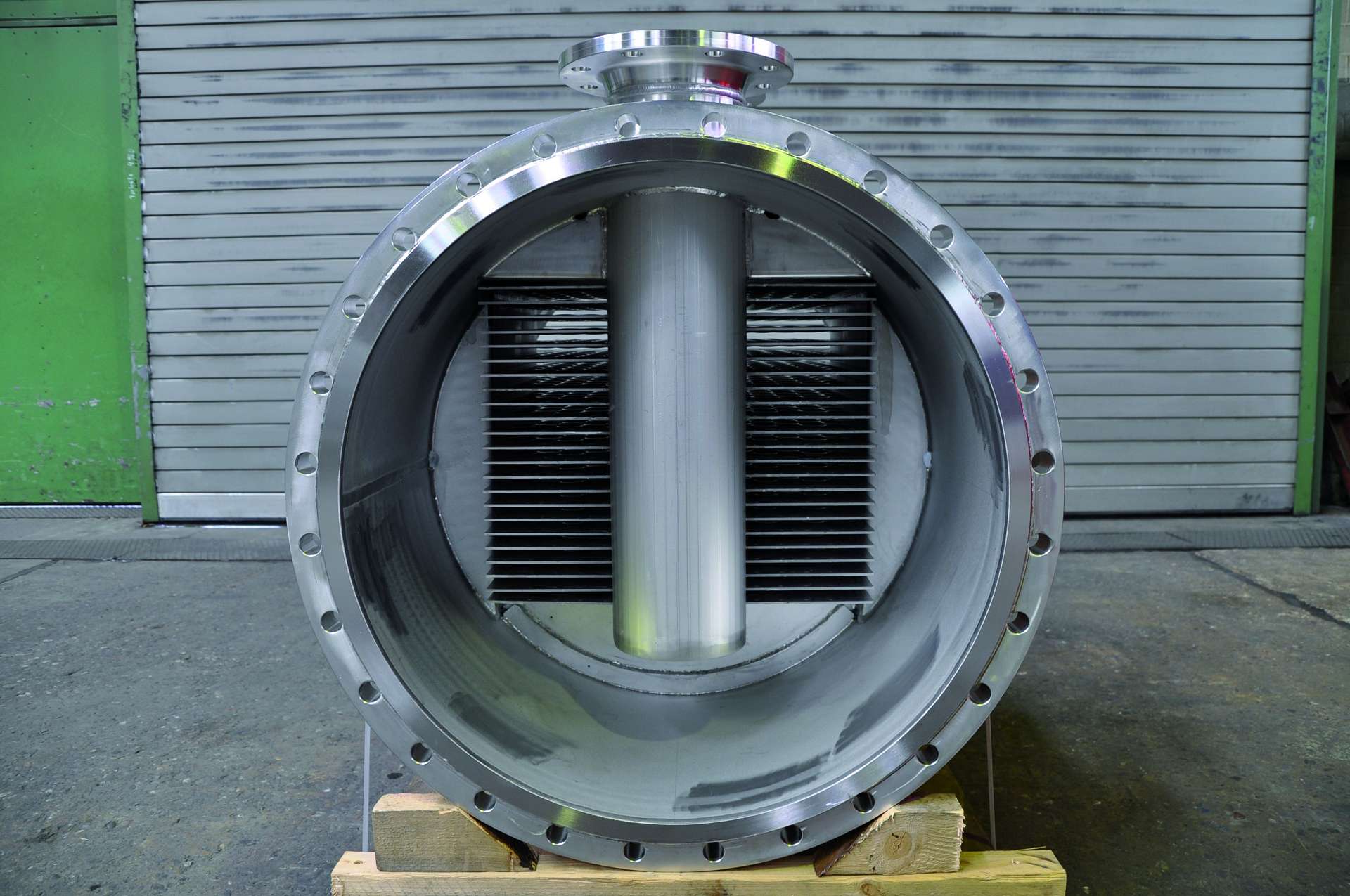
The two examples (head condenser design drawing / fin condenser design drawing) show two fundamentally different design features. In the head condenser, which forms the end of a column with an apparatus flange, the product to be condensed flows upwards and passes the plate pack, from above between the condenser plates. The condensate produced on the plates is discharged from the housing in liquid form, while the non-condensed residual gas leaves the process via a gas nozzle. A wide range of variations of this design are of course possible. With the plate fin condenser, the product gas flow is introduced directly into the plate pack via a large dimensioned inlet flange with fewer deflections than with a head condenser. The advantage of this flow guidance is the low pressure loss.
WTP-System for head condensers
WTP head condensers developed by LOB are an advanced version of heat exchanging plates. The special design of WTP head condensers minimizes their heat exchanging area by maximizing the heat transfer coefficient at the coolant end. No seals are necessary for preventing leakages, while strong turbulences in the WTP-head condensers result in an auto- cleaning effect. The heat exchanging surface can be reduced down to 2/3 that of a conventional tube-bundle heat exchanger, thus permitting easy and economical use at the head of a column. Another advantage of WTP-Condensers is the low pressure loss and the ability to easily clean the spaces between the plates.

