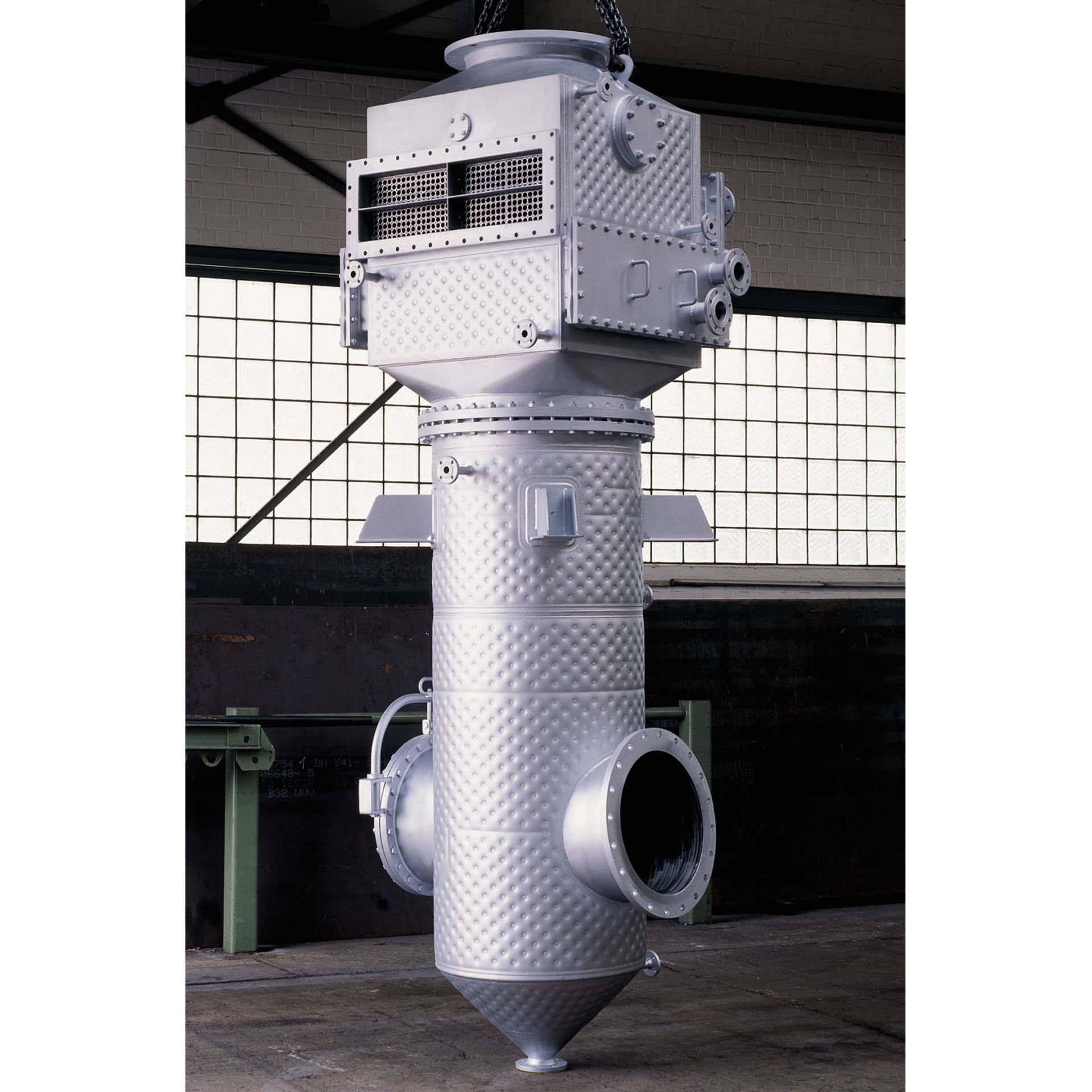
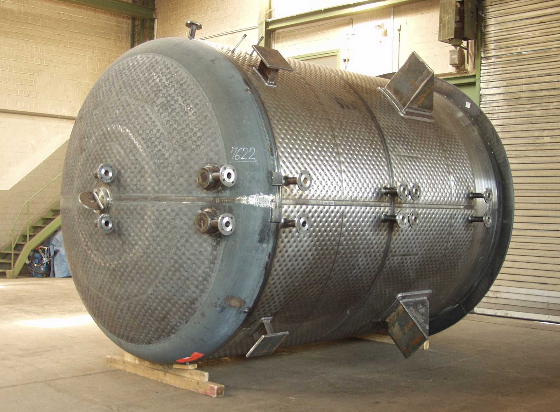
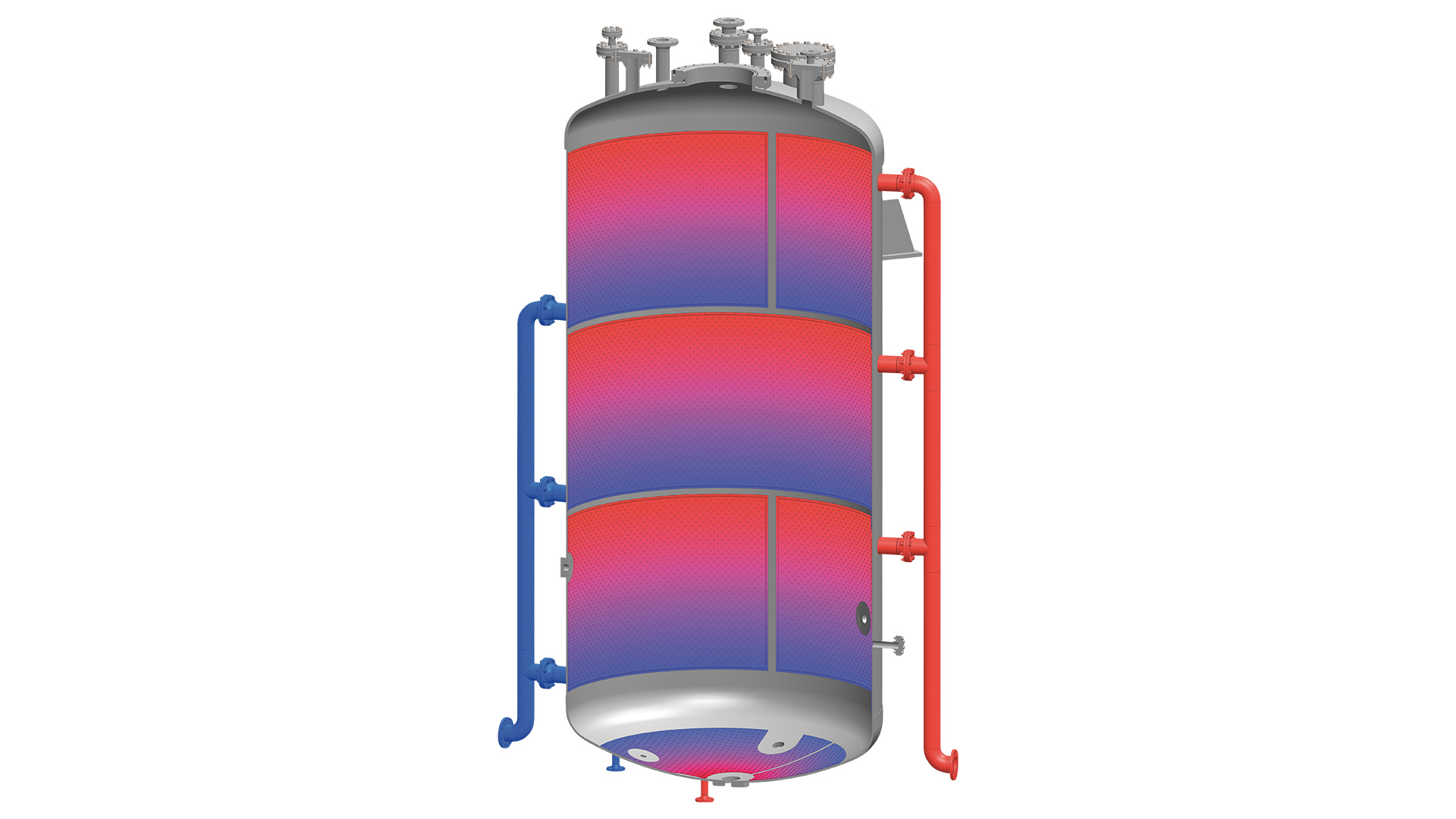
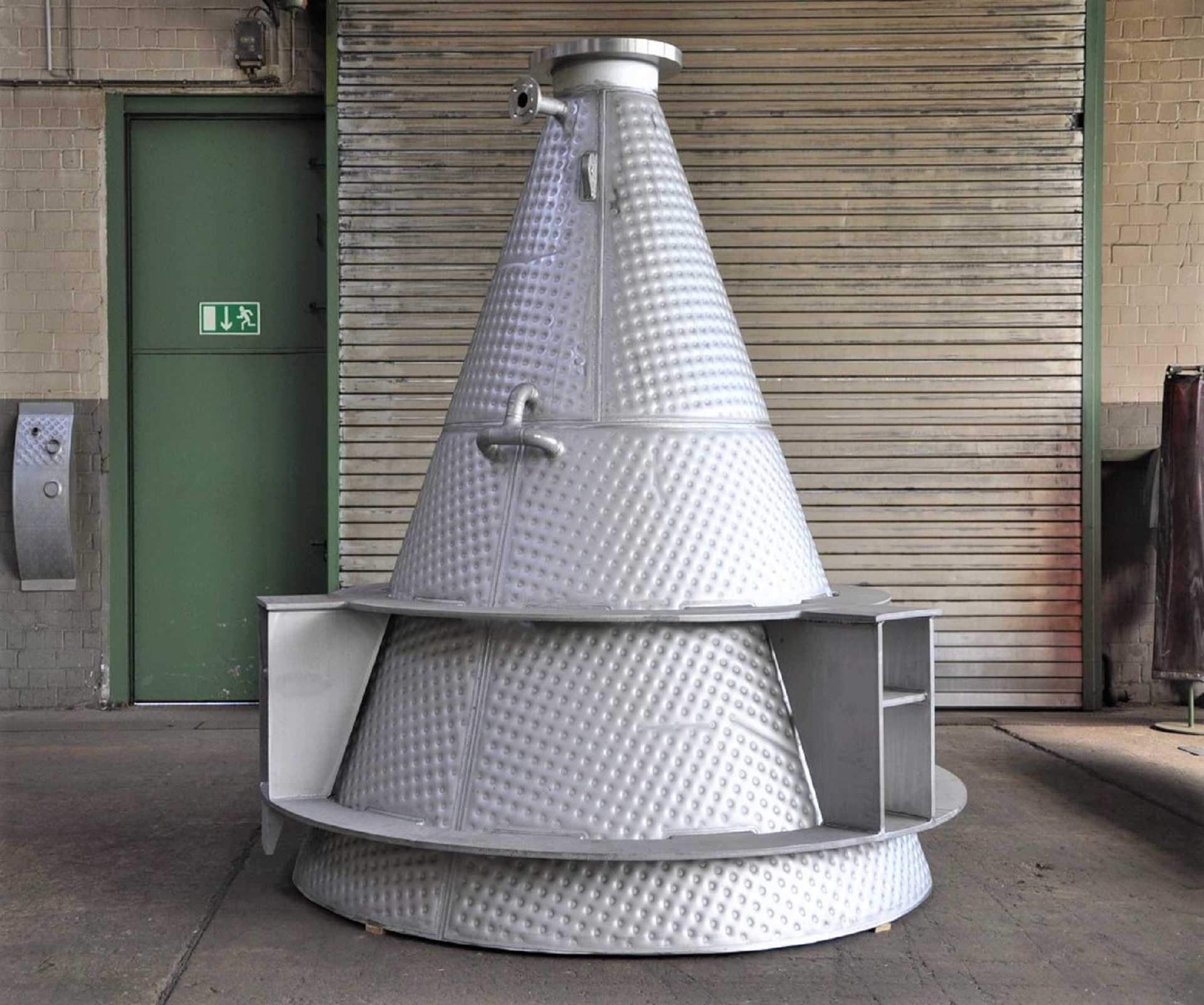
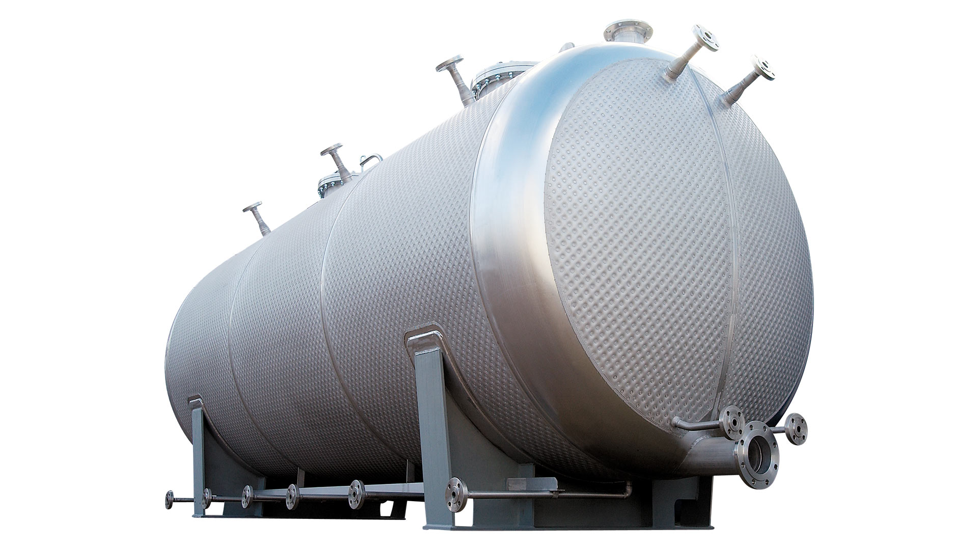
The WTP (heat exchanging plates) system is a tempering concept which serves as an economical alternative to conventional chemical devices such as the half-tube coil and double-jacket. Compared with these two designs, the WTP- system® offers a large number of advantages:
- Lower purchase price
- Lower operational costs
- Better heat transfer
- Faster heating
- Better control characteristics
- More efficient utilization of the heat transfer medium
- The performance of existing installations can be raised without the need for additional space
- Supply lines and pumps can have smaller dimensions
- Complex geometries are possible
- All installation positions are possible
- Lower weight
- Connectors can be retrofitted easily
- Clamping plates can be retrofitted
- Ideal for flat surfaces
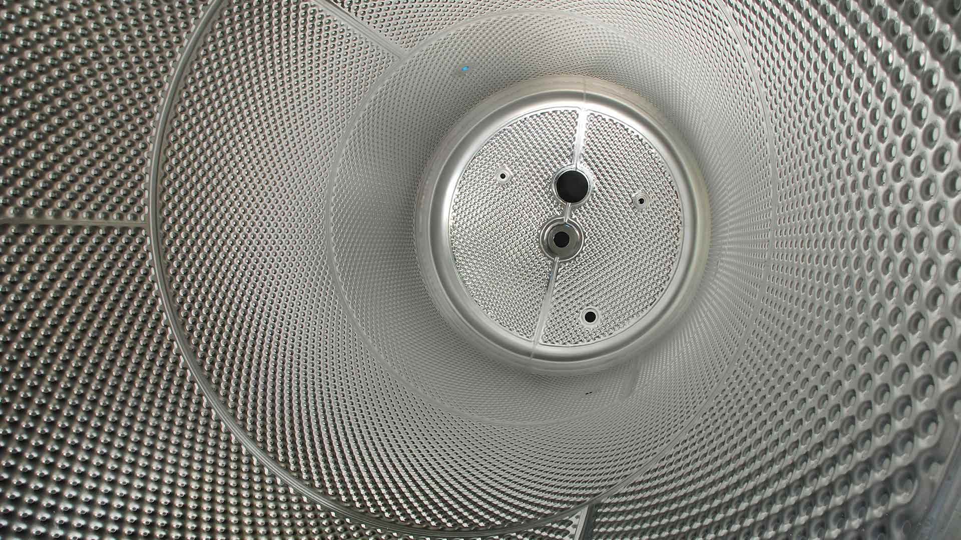 WTP-System® on the inside
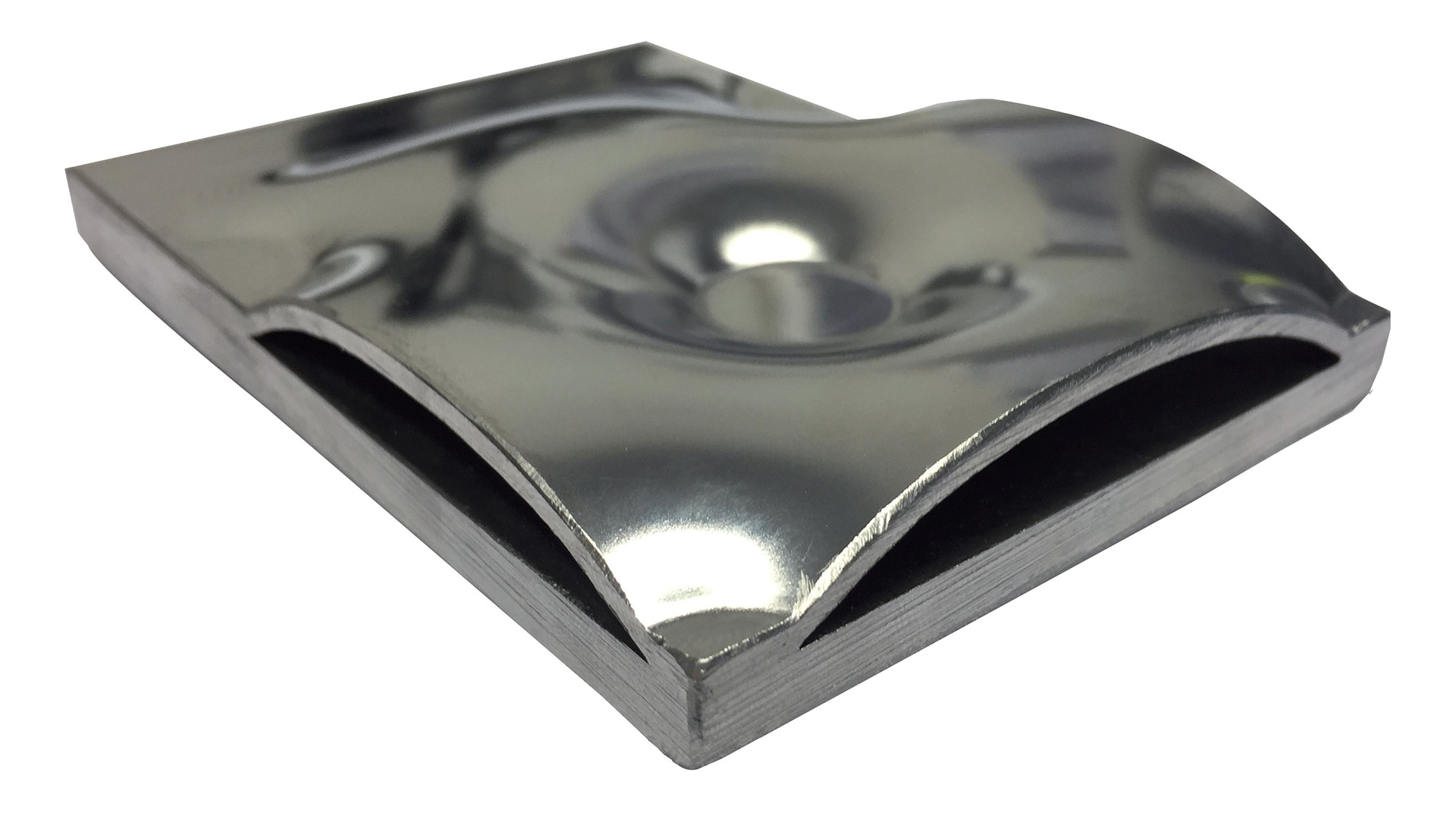
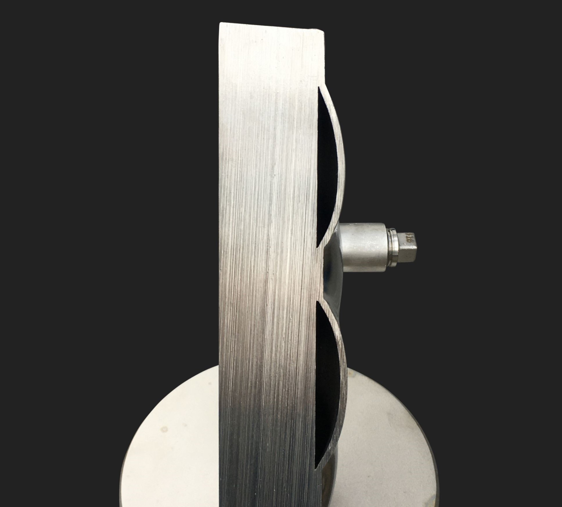
The WTP-system® is based on the following principle: Prior to forming, the pressure vessel jacket is coated with an outer jacket which is up to 2 mm thick and bonded by means of laser welding. After the vessel has been finished, the outer jacket is expanded through internal pressure, thus resulting in the creation of homogeneous cavities which can be used to conduct various heat transfer media.
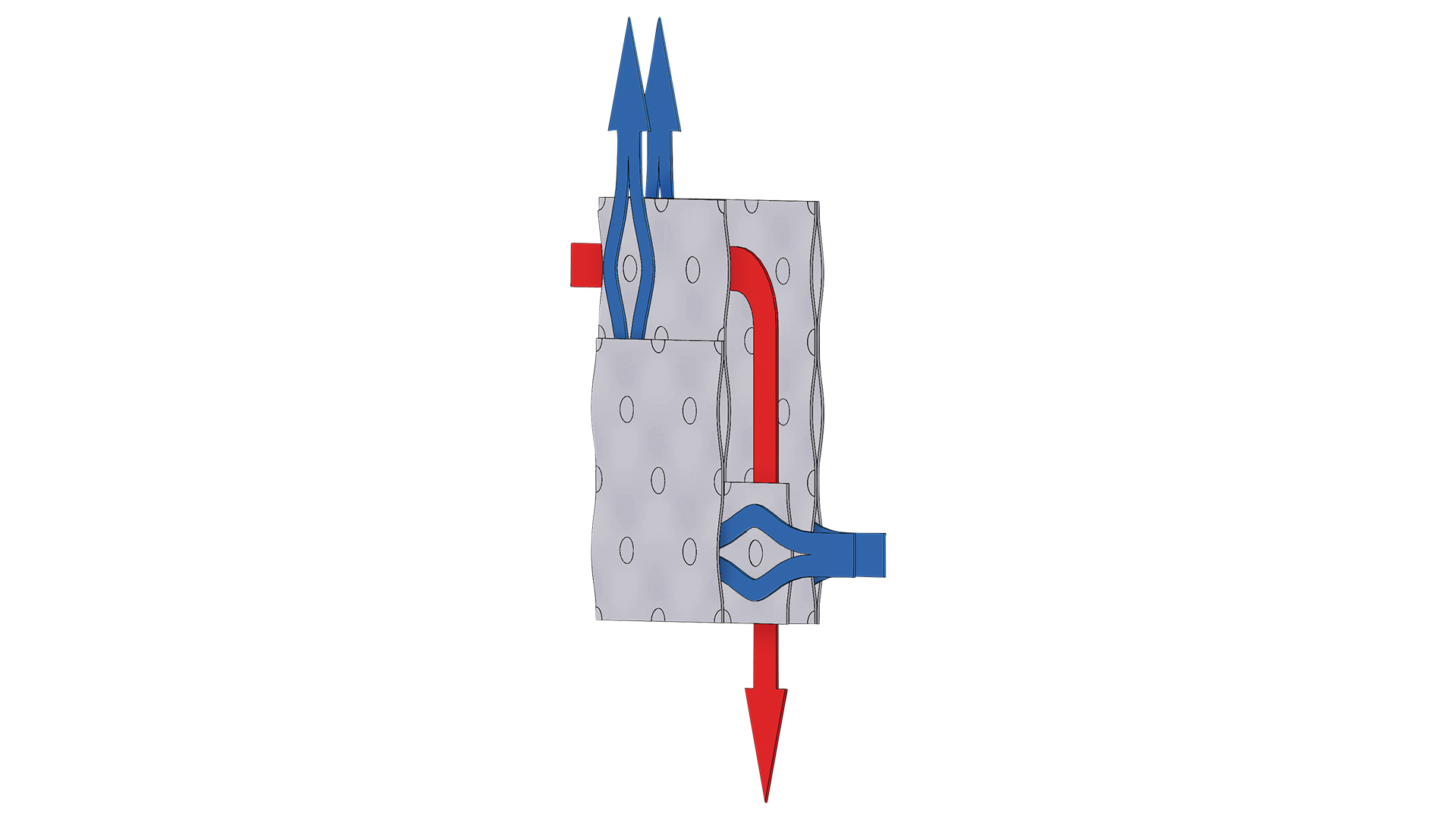
Gases as well as liquids can be used as heat transfer media. The WTP-system has a maximum operational pressure of over 50bar and maximum operational temperature of more than 300°C. In the case of liquids, forced guidance takes place through the laser seam (which joins the individual welded parts) in order to ensure a uniform distribution of the heat transfer liquid inside the jacket.
The WTP-system® is made of austenitic steels from groups 6, 7 and 8 (for example, 1.4571, 1.4539, 1.4462).
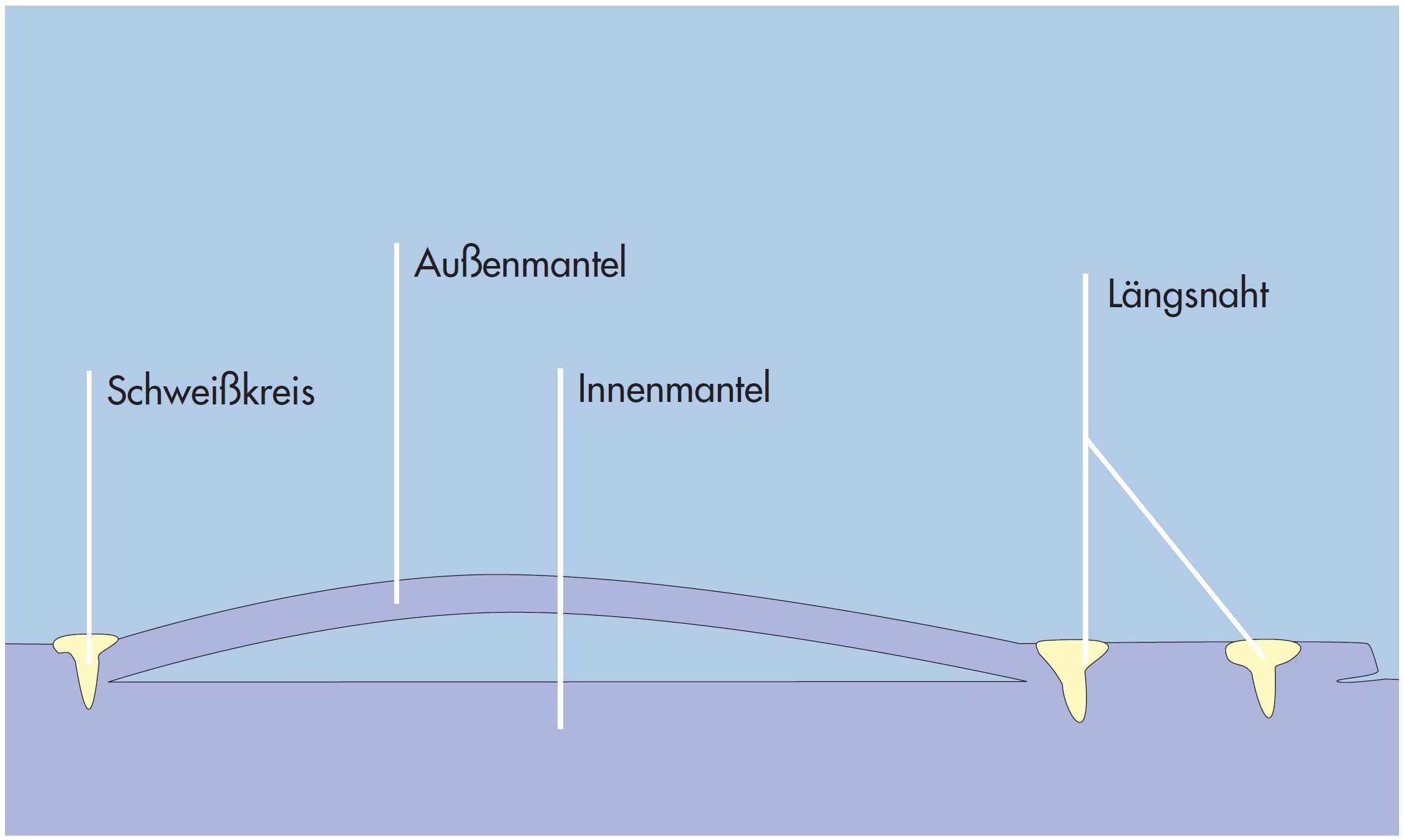 Welding connection
As the WTP-heating system is not designed on any mathematical principle and used preferentially for installations which operate in accordance with DGRL, destructive testing is used in this case. The samples, which are identical with finished parts in terms of shape and welding pattern, must meet the following criteria:
In accordance with DGRL, each sample must withstand 5 times the excess operating pressure, multiplied by the k-value at the room temperature and divided by the k-value at operating temperature. The ASME code requires the system to withstand 6 times the excess operating pressure. Calculations for a pressure vessel designed in accordance with DGRL and equipped with a WTP-system® need not take this system into account. Due to the smaller flow cross section, which is smaller than the cross section of a pipe DN100, the WTP-system® is assigned to DGRL category 1, in accordance with diagram 6 or diagram 4. The tests are carried out due to modul A, which states that no more future tests will be needed.
The bursting behaviour of the WTP-system® is interesting in this context. If the system bursts, only one or two welding rings are affected (Figure 1), thus permitting repairs to be performed easily. Investigations of samples after bursting do not reveal cracks in adjoining welding rings or other alterations in the microfinish. Connectors can also be retrofitted (Figure 2).
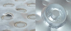 Figure 1 Figure 2
According to the results of our tests, extremely low pressure losses are exhibited by an ideal design (in terms of welding ring matrix, welding ring diameter, cushion height, heat transfer medium guidance and inflow). Experiments involving a test vessel (diameter 1,900mm; cylinder height 1,000mm) and conducted jointly with the University of Applied Sciences Cologne resulted in a pressure loss of less than 0.14bar/m at a volumetric flow rate of 10m3/h.
The tests also indicate a uniform pressure throughout the system heightwise, confirmed by the homogeneous flow through it. The low system volume makes it possible to achieve turbulent flows already at low volumetric flow rates of the heat transfer medium, thus resulting in outstanding heat transfer characteristics and excellent  values. Flow rerouting and bottlenecks increase the pressure losses.
During planning, special attention needs to be paid to the design and positioning of the inlet and outlet connectors which have a significant effect on the pressure losses and functionality of the system. For example, the  value is influenced notably by the number and dimensions of the inlet and outlet connectors. On the basis of our test results, we have developed formulae which allow us to not only calculate, but also guarantee the performance and maximum pressure losses.
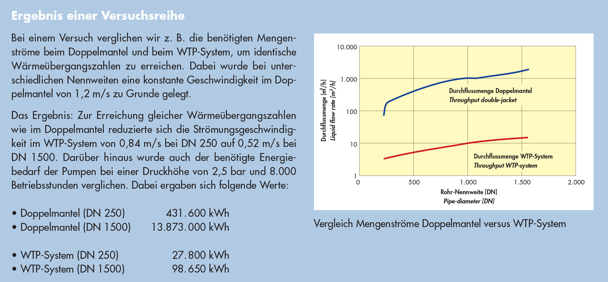 WTP-System® and double jacket comparison
During a series of tests involving an application of steam, we were able to achieve  values of up to 5,000 W/(m2 K) by appropriately distributing the steam and condensate connectors. The heat chart specifies
  values of between 1,100 and 1,600 W/(m2 K) for half-tube coils. This means that the heat transfer coefficient here is 50 % higher than that of half-tube coils; naturally, this also influences the heating period and, consequently, the efficiency.
This proves especially important for existing installations, from which the performance can be increased without the need for spatial modification by replacing vessels possessing a conventional heating system with vessels possessing a WTP-system®. As this system is able to achieve turbulent flows at a very early stage, the quantity of heat transfer medium it requires is thus also notably low. As a result, the dimensions of supply lines and pumps can be reduced. Due to its low volume, the WTP-system® also exhibits excellent control characteristics.
As regards retrofitting: Existing vessels can be retrofitted with the WTP-system® by attaching clamping plates (see photos below). Heat transfer can then be improved by applying heat-conducting cement. However, the heat transfer coefficient of a WTP-system® configured in this manner is not ideal, rather suitable mainly for a certain temperature level.
 WTP-Clamping plates
